* Amateur Radio on
Anglesey *
Anglesey is a very radio active
area! The
Island boasts an excellent club, the Dragon Amateur radio club, which
meets on the first and third Mondays of each month at the Canofan
Esceifiog, Garewen. The current membership is around 40 members and we
provide training for each level of the amateur radio licence.
My own location near the village of Carmel, is ideal from the radio point of view, being some 350 feet above sea level, one of the highest points on the island, which permits a clear line in all directions.
My shack details are as follows (In 2004):
The rig is an Alinco DX77, which I normally work (100W) into wire dipoles for 160, 80 and 40M. A recently completed tower project now gives me an Adex tribander on a 45' steel tower with Create rotator. On occasion I use a long wire, in conjunction with an MFJ 949E matching unit. Also available for receiving is an Eddystone radio 1830 rx. and an AR3000A scanner. I now use a computer logging system. The logging programme is home-brewed. This is necessary since I run linux on a Raspberry PI and all the popular logging programmes require the dreaded PC/Microsoft combination (ugh).
I started on the air as MW3CVQ, and my current callsign is MW0SEC.
Have a look inside the shack:

The shack is built on a mezzanine floor inside one of the two barns
at the QTH, which is a 17th. century farm.
The barn badly required re-slating and while I was at it, I decided to build a dividing wall and floor for the shack. Now fully insulated, it remains cosy even during the worst of the winter.
The complete roof required around 3000 slates, 10"x20" and was completed within one summer (phew!)
Latest update at August 2005:
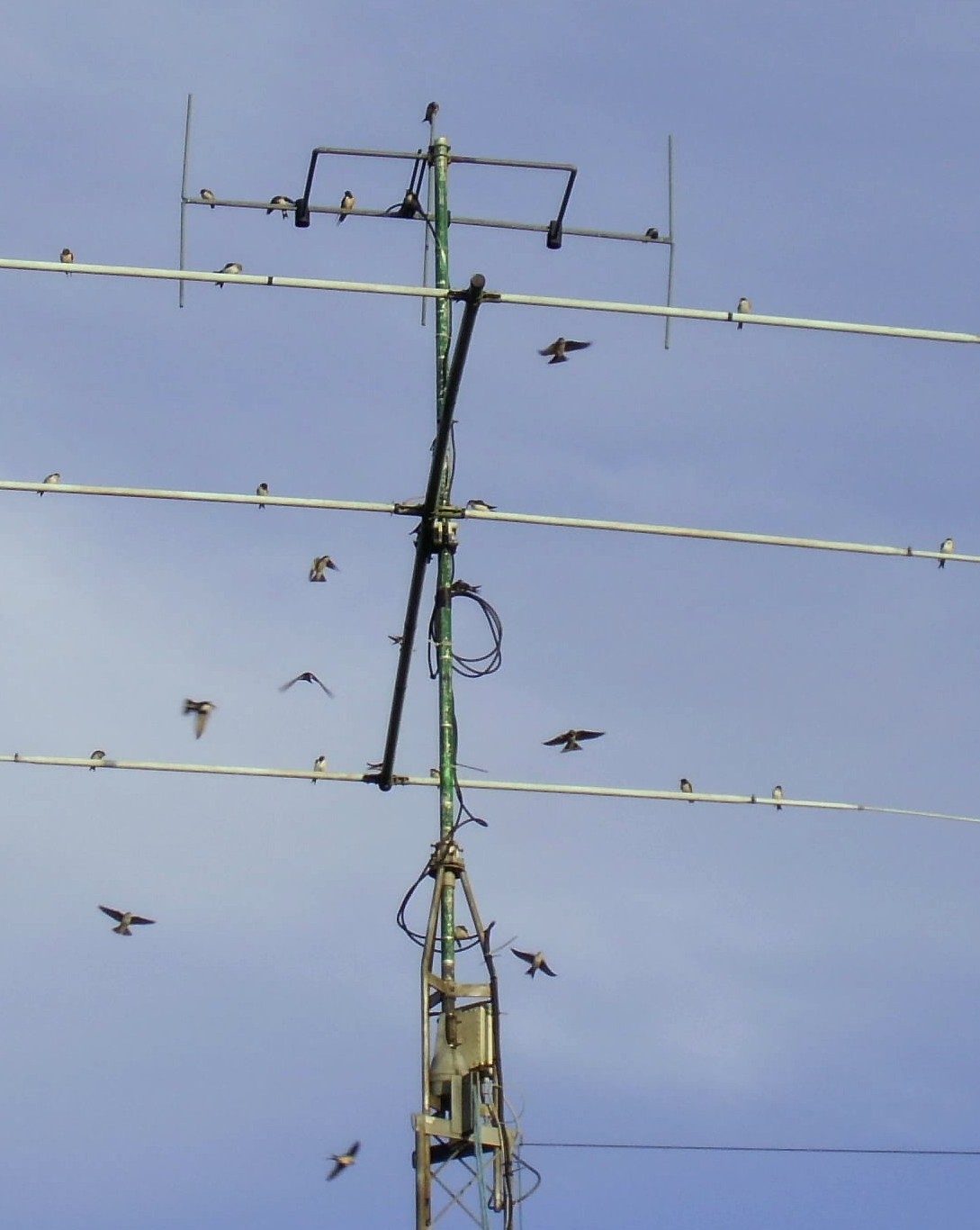
Now equipped with Ranger 811K linear (Built from the kit), which helps with difficult conditions. The tribander has been replaced in favour of a 20M telex hi-gain 3el. Yagi for optimum results on that band. It gets me nicely to VK and seems to be much more resistant to the winds of Anglesey.
Even later update at March 2007:
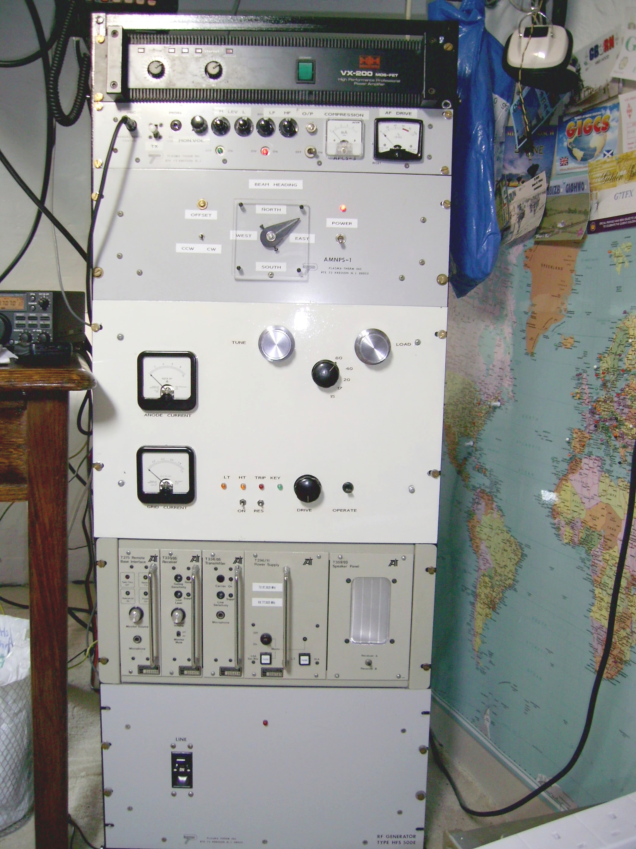
The Ranger has now been replaced by a home-designed linear based upon a GS35B and I have also built an audio processor. Both of these can be seen in the 19" rack in the pictures below. The item between the linear & it's PSU is a 4M rig made by Tait. Beam is now a 17M Yagi.
Projects:
HERE is a presentation I gave to the club on a build of a direct digital synthesis signal generator which includes the circuits. The software listing for it may be found HERE.
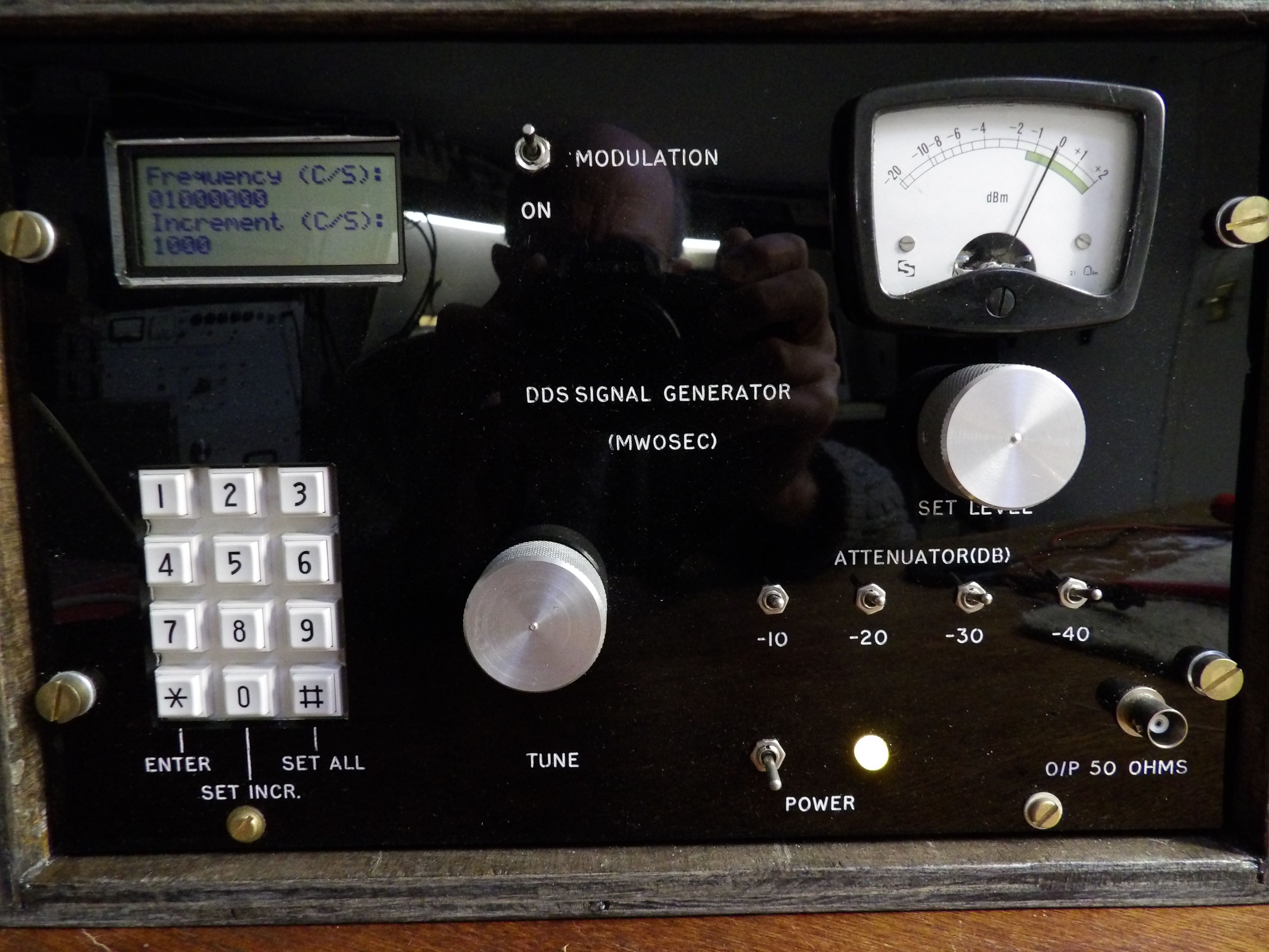
This shows the finished generator. Note that the tuning increment may be changed
without losing the currently selected frequency. I did not include much filtering of the output,
since harmonics can be useful in a signal generator. Setting the generator to the 70 mc/s
region for example,gives useful output on 2nd. harmonic for checking the 2M band,
although at this range, the amplitude can not be relied upon.
This describes a home made condenser microphone which I now use on HF:
First the principles:
A low loss capacitor will have a charge (Q) = Capacitance x Voltage, so once charged, if capacitance is varied, then the voltage across the capacitor will vary in proportion.
The capacitor is formed by a thin diaphragm (In my case cooking foil), stretched across a backplate and isolated from it by a small air gap.
The rear gap is sealed to air. This damps down the natural resonance of the diaphragm, giving the mic. a smooth frequency response. Below is the mechanical drawing of it:
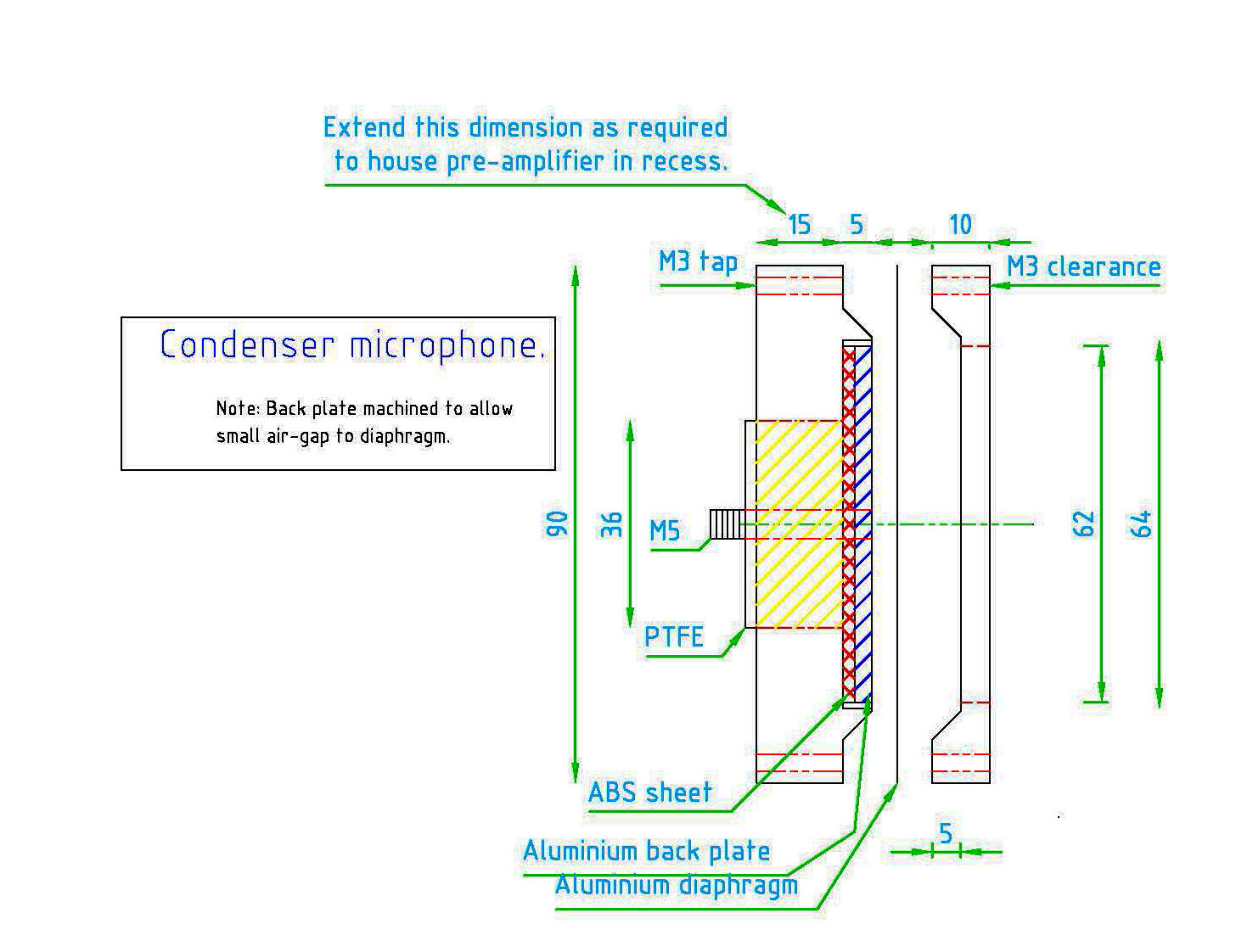
One
possible improvement would be to use a wider PTFE insulator, to reduce
the stray capacitance of the backplate to the case, which tends to
swamp the active element.
This should increase sensitivity.
This should increase sensitivity.
The mic. requires a polarising voltage
and a low-noise preamplifier. The resistor load across the mic. must be
as high as possible, since the combination of the small capacitance
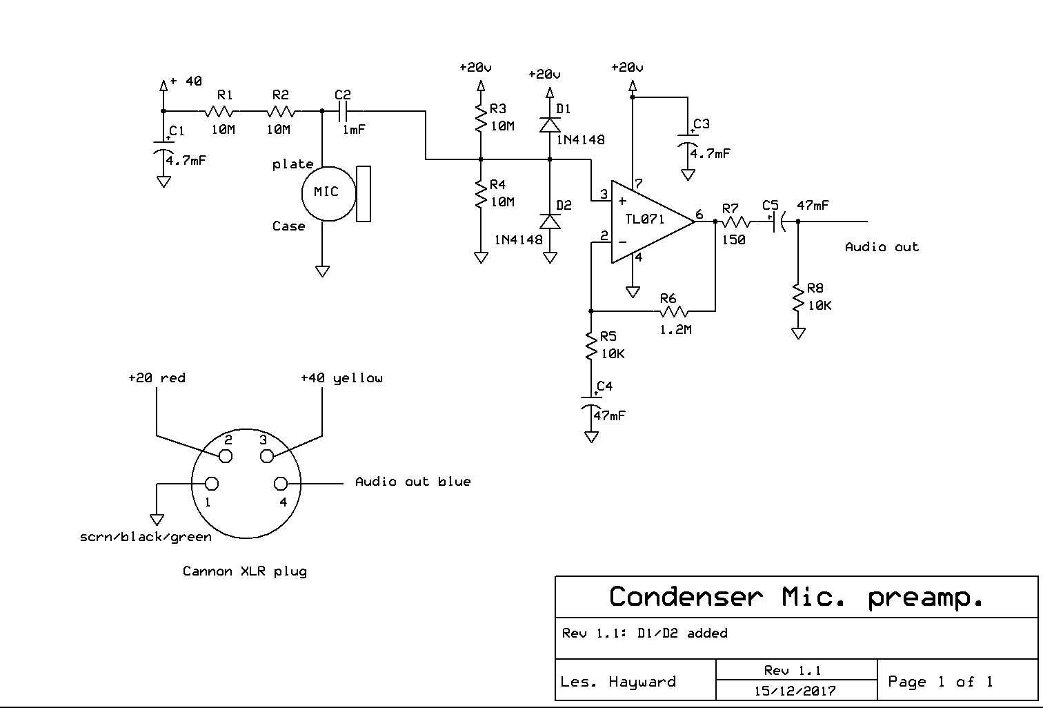
(around 100 pFd) in combination with any resistive load will form a first-order filter, limiting the bass response. Below is a circuit of a suitable preamplifier:
Note that C4 is larger than it need be - I had the component to hand! Due to the long time-constants involved, the amplifier takes around 30 seconds to
DC stabilise and produce output. D1 & D2 were added to protect the op-amp from high voltage transients. The power supplies need not be regulated and the voltages
are nominal. They must however, be very well smoothed and ripple free.
And here is a picture of the finished item. Note the use of part of an old military shell as the base weight:
A DDS Sweep generator (1-60 Mc/s):

The full details for constructing this (including software)
can be viewed HERE
73's!

